Stray light, along with detector sensitivity, work together to define the upper absorbance limit in dispersive UV/Visible/NIR spectrophotometers. However, the stray light value is the primary specification that limits the maximum sample absorbance possible for any instrument. Stray light is defined as any light that reaches the detector which is outside the spectral region isolated by the monochromator.  High stray light frequently leads to deviations from the Beer-Lambert Law, with subsequent inaccuracies in sample photometric values. In theory stray light dictates the dynamic range for most spectrophotometers; therefore, the lower the stray light specification, the more expensive the instrument.
Stray light can originate from anywhere either inside (optics) or outside (light leaks) the instrument. Spectrophotometers that are well designed should not have stray light from either leaks or errant internal reflections. Typically, the primary source of stray light is from the diffraction grating component of the monochromator. There are flaws in the regular lines etched on the grating as a result of the manufacturing process, and are the cause of most instrumental stray light. 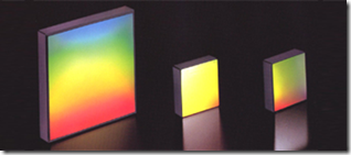 Modern holographic gratings produced by photolithographic processes have much lower stray light than the less expensive mechanically “ruled” gratings. To reduce stray light even more, two gratings can be used in series to achieve upper absorbance limits exceeding 6.
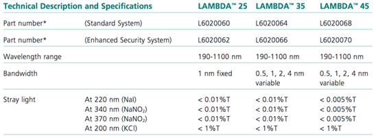
A stray light specification at several key wavelengths informs the user of the dynamic range of the instrument. The stray light specification is typically quoted as a percent transmission maximum for a specific wavelength. The insert below shows a typical specification sheet for three of PerkinElmer’s mid-priced spectrophotometers. The stray light specifications at the bottom of the chart.
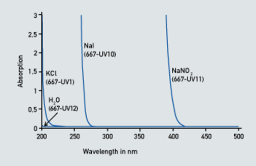
Instrumental stray light is measured through the use of short wavelength blocking solutions. These materials totally block all light at shorter wavelengths than the specified cutoff wavelength. When the instrument is set to a wavelength lower than the cutoff value, only stray light that is passed above the cutoff wavelength is measured. This, by definition is stray light. The absorbance cutoff spectra of several common stray light test solutions (approved by ASTM) as pictured below.
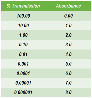
Stray light, by convention, is measured in percent transmission. This is not very useful when most users tend to think in absorbance, at least as far as dynamic range is concerned. As one can see from the conversion equation:
Absorbance = -log(%T/100)
absorbance is a simple -log transformation of the transmission value. The chart enables us to visualize the transmission/absorbance relationship over many orders of magnitude. From this chart we can easily see that a spectrophotometer with a stray light specification of 0.01 %T will not be able to measure any sample over 4.0 absorbance units. In addition to setting the highest absorbance, the stray light introduces a photometric error that increases in significance as the sample %T value becomes lower and approaches the stray light value.
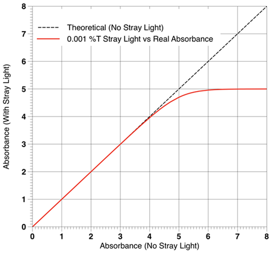
The plot below shows how stray light not only sets the upper absorbance level, but also is responsible for deviations from Beer’s Law. The black dotted line is the theoretical Beer’s Law relationship without any stray light affects; whereas, the solid red line has incorporated an instrumental stray light component of 0.001 %T. Note that the linear Beer’s Law relationship is maintained up to an absorbance of about 4. After a short region of increasing decline, the measured absorbances plateau as they approach the stray light values for the instrument. Stray light photometric artifacts always yield lower than actual absorbance values.
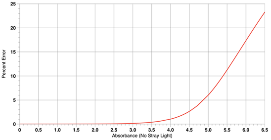
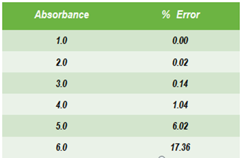
The percent error from Beer’s Law linearity due to the consequences of stray light is graphed below.
The value for the stray light in this plot is the same as the previous page, 0.001 %T. Note that the error does not become significant (i.e. 1%) until around 4 absorbance, One percent is typically the linearity cutoff, since above 1% the error increases dramatically with small increases in absorbance.
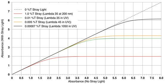
Pictured below are plots for various instruments having different stray light specifications. As you can see, the shape of the plots are similar with only the Beer’s Law linearity cutoff point and the stray light plateau levels being different. The utility of this type of plot is that it defines the dynamic range envelope of any instrument based on it’s stray light specification.
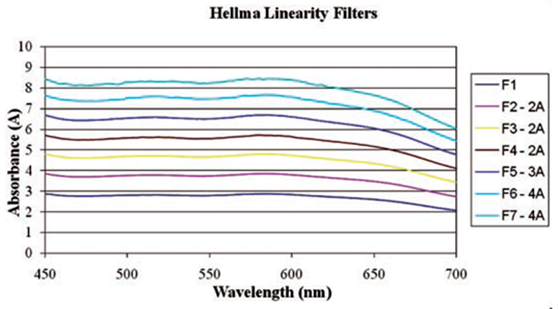
Now it is not unusual for a shiny new instrument to exceed the published stray light specification by a considerable amount. Modern high performance double monochromator instruments have stray light values permitting upper measurements in the 6 to 7 absorbance range. But 8.5, what’s going on below?
There exist a unique type of sample that appears to violate the stray light maximum for any instrument. These are samples that have a high absorbance level across an extend wavelength range very much like a high A neutral density filter. These samples have the unique property of acting as their own stray light filter; thereby, blocking stray light across large wavelength ranges. Not many samples have this type of absorbance profile. So if your sample has several absorbance peaks and returns to a low absorbance baseline in between, don’t expect to be measuring 8 plus absorbance values.
Related PerkinElmer Technical Literature:
Linearity Measurements in the Visible Region on a LAMBDA 850/950/1050 Using Hellma Linearity Filters
